IoT-PostBox v0.x
Legacy technical documentation for IoT-PostBox v0.x series (ESP8266 based). This generation focuses on ultra-low power consumption with hardware wake-up mechanism and basic WiFi connectivity.
Hardware Overview
| Top View | 3D Rendering | Bottom View |
|---|---|---|
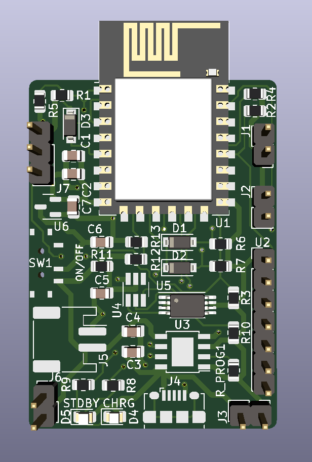 |
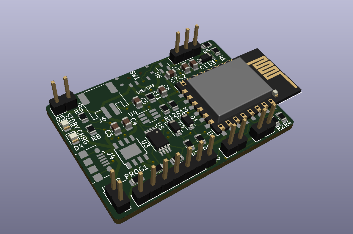 |
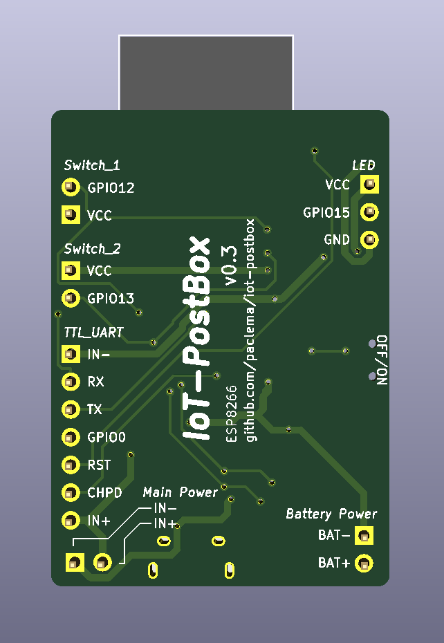 |
Key Features
Core Platform:
- MCU: ESP8266 (ESP-12F or ESP-07S)
- Connectivity: WiFi 2.4GHz with MQTT support
- Wake-up Method: Hardware reset via CH_PD pin (vs GPIO interrupt in v1.x)
- Power Optimization: Deep sleep with GPIO14 keep-alive mechanism
Power Management:
- Battery Charger: TP4056 with protection circuits
- Single LDO: ME6211 or MCP1700 for power regulation
- Battery Monitoring: ADC-based voltage sensing
- Protection: Overcharge, overdischarge, and overcurrent protection
I/O & Interfaces:
- Switch Sensors: Two hardware wake-up inputs (J1, J2)
- LED Support: WS2812B RGB LED strip (v0.3+)
- Programming: Populated UART and programming pins ready for external TTL-to-USB adapter
- Expansion: Basic GPIO access
Power Management Architecture
Hardware Wake-up System
The v0.x series uses a unique hardware wake-up mechanism optimized for ultra-low power consumption:
Switch Input ──── CH_PD Pin ──── ESP8266 Power Control
     │                                    │
     └──── GPIO14 ──── Keep-Alive Logic ──┘
Wake-up Process:
- Power Off State: ESP8266 completely powered down (CH_PD low)
- Event Detection: Switch contact pulls CH_PD high, physically powering on the ESP8266
- Keep-Alive Activation: Firmware immediately sets GPIO14 high to maintain CH_PD even if switch opens
- Notification Process: ESP8266 performs WiFi connection and sends MQTT notification
- Power Down: After configured time/completion, GPIO14 goes low, powering down the ESP8266
Power Management Options:
- Complete Power Down: GPIO14 low after notification (recommended for battery life)
- Deep Sleep Mode: Can be configured instead of complete power down
- Continuous Operation: GPIO14 remains high for always-on operation
Power Consumption:
- Power Off State: ~0μA (ESP8266 completely powered down)
- Active Mode: ~80mA during WiFi transmission
- Battery Life: Months to years depending on event frequency and configuration
Power Input Considerations
- Only one power source can be connected at a time: USB charging, J3 (PowerIn), or UART programming connector
- Connecting multiple power sources simultaneously can damage the board
- This simple design lacks protection against multiple power source conflicts
- Always disconnect one power source before connecting another
Battery Charging Configuration
TP4056 Charger IC:
- Input Voltage: 4.5V to 5.5V (USB 5V)
- Charging Current: Configurable via RPROG resistor
- Protection Features:
- Overcharge protection
- Overdischarge protection
- Overcurrent protection
- Battery reverse polarity protection
RPROG Resistor Selection:
$$I_{charge} = \frac{V_{PROG}}{R_{PROG}} \times 1200 \quad (V_{PROG}=1V)$$
| RPROG (kΩ) | Charging Current (mA) |
|---|---|
| 10 | 130 |
| 5 | 250 |
| 4 | 300 |
| 3 | 400 |
| 2 | 580 |
| 1.66 | 690 |
| 1.5 | 780 |
| 1.33 | 900 |
| 1.2 | 1000 |
Programming & Initial Setup
Hardware Requirements
Programming Methods for ESP8266:
Option 1: TTL-to-USB Adapter
- Repository: iot-postbox/ttl_to_usb_adapter
- Purpose: Converts DTR/RTS signals to ESP8266 boot sequence
- Features:
- Automatic boot mode selection via DTR/RTS
- CH_PD control via dedicated jumper
- Works with any FTDI breakout board
Option 2: Integrated USB Bridge
- Alternative: USBtoUART Bridge - Complete USB programming solution
- Advantage: Single device solution with integrated USB-to-UART conversion
Connection: UART pins populated on PCB for direct programming interface
Programming Setup:
Option 1: Using TTL-to-USB Adapter
- Connect FTDI Breakout: Attach a USB to UART FTDI breakout board to TTL-to-USB adapter
- Connect to PCB: Attach adapter to ESP8266 UART pins on PCB port
- Set Boot Mode: Configure adapter jumper for programming mode
- Upload Firmware: Use Arduino IDE or PlatformIO
Option 2: Using Integrated USBtoUART
- Direct Connection: Connect USBtoUART bridge directly to ESP8266 UART pins
- Automatic Boot: Device handles boot sequence automatically
- Upload Firmware: Use Arduino IDE or PlatformIO
Firmware Configuration
The IoT-PostBox firmware is built using the Arduino-ESP8266 framework and PlatformIO. Depending the ESP8266 module used (ESP-12F or ESP-07S), you will need to select the appropriate board environment. Further instructions and documentation can be found in the Firmware page.
Interactive Bill of Materials
Note
Explore components to view details and placement information. View Fullscreen 🔍
Technical Documentation
3D Model
Note
Explore the 3D model interactively. Use mouse to rotate, zoom and pan. View Fullscreen 🔍
Detailed Pinout Reference
Switch Sensor Inputs
Event Detection Connectors (Switch_1 & Switch_2):
| Pin | Signal | Function |
|---|---|---|
| 1 | VCC | Reference voltage |
| 2 | GPIO | GPIO input for switch detection |
Connection Notes:
- Connect switch between VCC and GPIO pins
- GPIO detects circuit closure when switch is activated
- Circuit closure triggers CH_PD wake-up sequence
Power & Charging Connectors
Battery Connector (Battery Power):
| Pin | Signal | Function |
|---|---|---|
| 1 | BAT- | Battery negative (Ground) |
| 2 | BAT+ | Battery positive (3.7V Li-Po) |
External Power Input (Main Power):
| Pin | Signal | Function |
|---|---|---|
| 1 | GND | Ground |
| 2 | VBUS | External power input (5V) |
USB Charging:
- Connector: Micro-USB (depends on version)
- Input: 5V for charging and operation
- Current: Up to 1A charging (RPROG dependent)
LED Strip Connector (v0.3+)
WS2812B LED Strip (LED):
| Pin | Signal | Function |
|---|---|---|
| 1 | VCC | Power (3.3V) |
| 2 | GPIO15 | WS2812B data signal |
| 3 | GND | Ground |
Programming & Debug Interfaces
UART Pins Extension Port (TTL_UART):
| Pin | ESP8266 GPIO | Function |
|---|---|---|
| 1 | GND | Ground |
| 2 | RX | UART receive (GPIO3) |
| 3 | TX | UART transmit (GPIO1) |
| 4 | GPIO0 | Boot mode selection |
| 5 | RST | Hardware reset |
| 6 | CH_PD | Chip enable |
| 7 | 3V3 | Power supply |